The Wye Modules
by Peter A. Vanvliet
This page is an article about the club's wye modules. Jack built three modules that make up a double-track wye, matching the other modules used by the club. The significance of these modules is that they open up a whole range of possibilities for the club's set-ups.
Jack told me he started designing the modules in 1996, and started building them around 2004 or 2005. They resided in his garage for a number of years after their construction until their space could no longer be justified. They were relegated to the outdoors, although they were protected from the heavy Houston rains. As a testament to Jack's ability to lay high-quality track and build solid bench work, the modules were still in excellent condition in February 2010, when I picked them up.
I volunteered to take over the modules so that they could be completed. The first three photos show the modules as I received them, showing all the work Jack had done to them. The modules are constructed using standard 3/4-inch thick plywood. The curved wooden edges were partially cut through to allow the wood to bend. The modules are heavy, but one person can carry one. The track is laid on Homasote.
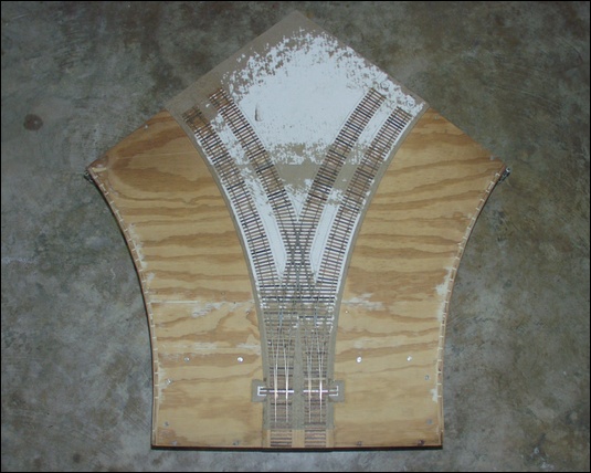
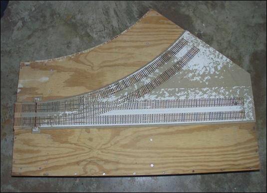
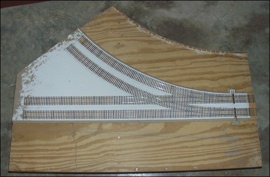
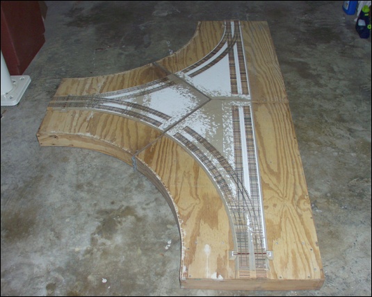
The next photo shows the three modules moved together on my garage floor. The completed section covers an area 8 feet long and 5 feet wide. It is a large set-up. As you can see from this configuration, the straight double mainline can add to or replace an 8-foot section of track to our club's layout. The wye can then be turned inward to allow us to have a set of modules inside the layout to set up and tear down trains. The modules can also have the wye facing outward to additional modules forming a branch line. Also, two of the modules can be used to replace one of our standard corner modules so that the straight section of the wye can go out to additional modules, again forming a possible branch line.
These are two close-up photos of the turnouts. The first is on one of the standard turnouts, and the other is of the wye turnouts.
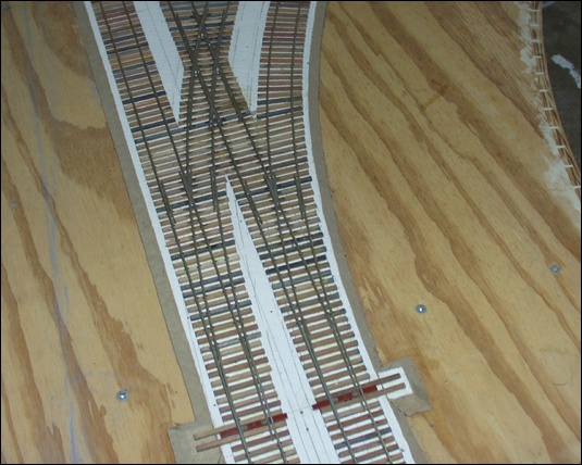
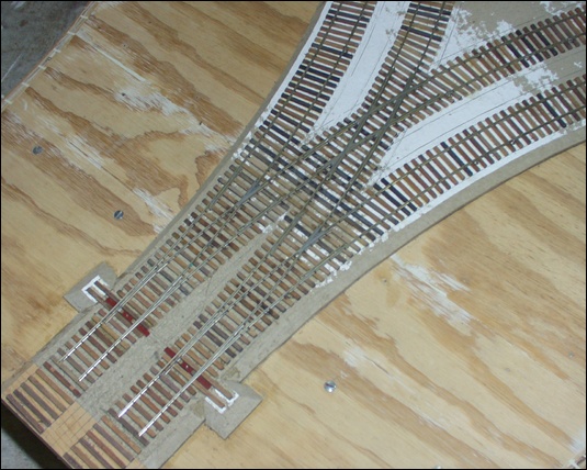
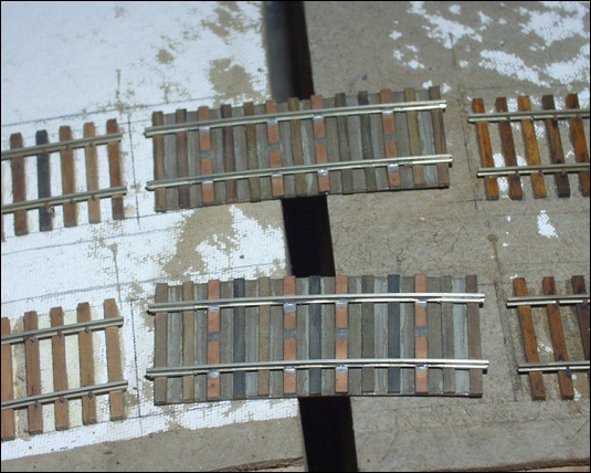
For our club modules we use short pieces of rail that we install after the layout is set up to complete the track of the various modules. However, for the connections between these wye modules, since they are curved, Jack made some special track segments that fit perfectly between their modules. I didn't have the modules connected to each other in these photos, but you get the idea in the next photo. These are thin pieces of wood onto which wooden and PC ties have been glued. Those ties are half-height so that the rails match up with the module rails.
Standard door hinges are used to firmly connect the modules together.
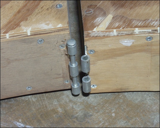
This photo shows the three modules set up. It wasn't trivial, but it only took me a few minutes. Each module requires three legs. Once the legs are installed, the modules can be moved together and the pins can be inserted to permanently attach them together. There are two hinges on the sides and three underneath the modules.
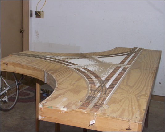
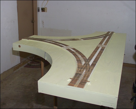
The set-up was done so that I could check everything to make sure the tracks still lined up, the hinges were still in the right position (i.e. no wood warping), and to get an idea of what needs to be done next. I decided that while they were set up, I'd put a first primer coat of paint on the tops and sides of the modules. This will help protect the wood and screws from further exposure to the elements.
On September 29, 2010, I completed the wiring and electronics work on the three modules that make up the wye. To prove it, I shot a quick video demonstrating a short train traversing the entire double-tracked wye. I had build three 18-inch extensions to allow the train to go beyond the turnouts near the end of each module. They are a stand-in for other club modules, and allow me to test the set-up in my garage. It's been a long few days trying to get the modules ready in time for the show, so please excuse my tired look. :-)
As mentioned in the video, I used six Fast Tracks Bullfrogs to allow for manual control of the turnouts and controlling the polarity of the turnouts' frogs. There are also six crossing frogs whose polarity must be controlled, which I did via the Tam Depot Valley Hex Frog Juicer, also sold by Fast Tracks. For the control rods to access the Bullfrog throw mechanisms I installed parts from the Fast Tracks Bullfrog Dual Actuator kits. One downside we have discovered with these control rods is that you must be very careful with them when placing the modules on their side during set-up and tear-down. The control rods do have some give, but there is an upper limit to how much they can flex.
The center (curved track) module is electrically isolated from the two straight modules and the track power is controlled via one section of the Digitrax PM4. I had an unused PM4 available which is why I used it, but if I had to buy something for this project, I would have selected a simpler, cheaper DCC auto-reverse module, such as the AR1 by Digitrax. The PM4 requires an external power source and a connection to the ground of the DCC Command Station, so there is some extra complexity involved.
The Hex Frog Juicer is almost trivial to use. Two of its screw-type connectors need to be connected to the DCC bus, and the remaining six connectors each feed one crossing frog.
These circuit boards were installed, via screws, to the underside of the center module so that all the wiring is kept in that module. There is a set of wires that connect it to the straight modules to connect to the DCC bus under the straight modules, a single wire to be connected to the ground of the command station, and two wires each going to the crossing frogs of the straight modules. Of course, then there are also the standard DCC bus wires that are common to the S-MOD standard. Note that the standard DCC bus wires coming off of the center module to go on to additional modules connected to it, need to be connected directly to the straight modules' DCC bus line, because only the center module is to be isolated and controlled by the automatic reversing section; all other modules on the layout are directly connected to the main DCC bus line.
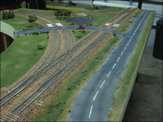
I spent three weeks working full-time on the modules to get them ready for the big show. I didn't want to just have track, so I put in the extra effort to have the modules appear to be finished. The photo below was taken the day before the big show. The small interconnecting pieces of track between the modules were not installed when I took the photo. To get them to this stage, I marked off the roads, followed by painting the non-road areas. While the paint was still wet, I put down some basic ground foam. The roads were made using vinyl spackling. I put about three layers down. The final layer was sanded down to provide a smooth surface. Some surface imperfections were left in to give the road an aged, worn look. I also spent several days ballasting the track. There is 42 actual feet of track on these modules, so that took some time. I again put more ground foam (various colors now) on top of the existing ground foam. It was all heavily sprayed down with alcohol and then 50/50 white glue and water. The road was completed by following an article in one of Dave Frary's books. I painted the road surface a basic earth color. While the paint was still wet, I poured an even layer of "PRR fine ballast" (left over from my N-scale days) on top of the paint. The next day I painted the road the light gray color you see along the edges. After that, I painted the darker gray to give the road more of an aged look. I then pulled out the airbrush, and spray painted the oil streaks down the lanes. After that was dry, I put masking tape and sheets of paper down to be able to airbrush the lane divider lines (I used Polly Scale white for that; lines were white prior to 1972). I completed the road with a little bit of weathering chalks over the lines where traffic normally flows. The final touches to the modules were to glue down some bushes and to drill some holes for some left over N-scale trees (these will eventually be replaced with proper scaled trees). I also spent half a day cleaning the track, scraping off all the glue residue and paint residue from airbrushing the sides of the rail. Oh, and I built four timber grade crossings. It all was hard work, but I had a blast. By the time of the show, I was exhausted, but I think it was worth it.
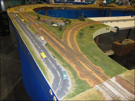
October 16, 2010 was the official debut of the wye at the "Big Texas Train Show" in Houston, Texas. This was a two-day event that drew thousands of people. Our club had a prime spot in that we were right at the public's entrance. The show was open on Saturday and Sunday, but we did our set-up Friday night. The modules were pretty easy to set up (I had been doing that nearly every day for the past 3 weeks to complete the scenery work), and the electronics all co-operated so that we were able to get an engine to run Friday night. The photo below was taken Saturday before the show opened. Ria had built two structures that we put on the layout. We also put a number of automobiles and temporarily glued some people on the modules. In the upper right hand corner of the photo you can see the third leg of the wye. The club put up a temporary door and some temporary S Helper Service track to allow trains to be set up in the center area of the layout, and then move out onto the layout via the wye. Jerry had built some front fascia panels for the wye modules, which are shown in the photo.
This completes this article on the wye. We are going to install a Digitrax UP5 panel so that club members can plug in a throttle while working on the wye. We have also been discussing ideas for the center "yard" area and the need for additional modules to enhance that area.
For more information about how to wire a wye, see the Wiring for DCC article by Allan Gartner.