The Third Leg
by Peter A. Vanvliet
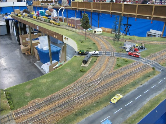
In 2010 I completed the three modules that make up the club's double-track wye. When they were completed, we were faced with the issue of what to use for track for the third "leg" of the wye. Our typical set-up has the wye inserted in one of the short edges of the rectangularly-shaped layout. For most shows we have one or more modules available to attach to this third leg. However, occasionally we have a show that uses up all of our modules. At the "Big Texas Train Show" of 2010 we improvised and used a door on top of some boxes with some S Helper Service track taped to the door, relying on the rail joiners to conduct electricity. The solution worked, but it was definitely not something we wanted to repeat in future shows.
In September 2011 this issue surfaced again in light of the 2011 version of the "Big Texas Train Show". I decided that this was as good of a time as any to build additional modules to form this "third leg" of the wye. It was recommended that I'd build one 4-foot long module, but there's really not much one can do on a 4-foot module in S-scale. I decided to build three 4-foot modules, to make a total of 12 feet of staging tracks. I decided on three 4-foot modules rather than two 6-foot modules because of our truck bed, which handles 4-foot modules well. The three modules that make up the wye are also 4 feet long, so it is a perfect fit. The truck bed can handle up to 8 modules, so the 6 that make up the wye and this new third leg will fit easily.
The diagram below is the track plan I came up with and obtained consensus with from the group. We had several requirements to enhance the usefulness of the wye modules. Since the wye is a double-tracked wye, you cannot use it to simply turn a train on the same track (see the wye article on this web site and trace it out; you'll see). To make it possible to have any train from either of the two main lines be turned and head into any direction, a crossover set of turnouts was required on the third leg of the wye. Additionally, we found that heading an engine into the stub end of the third leg of the wye prevented it from escaping out of the track while a switcher moved the cars it delivered out of the way. The second crossover near the end of the third leg was added to make this move possible. The requirement was to allow a double-header set of engines to be able to escape, so the turnout was placed approximately 20 inches from the end of the track. These two crossovers also make it possible to do a run-around move. Finally, we wanted additional staging tracks, mostly for setting up trains. Each main track got a turnout to make for a total of four staging tracks. The average freight train can be set up in one staging track, but extraordinarily long trains can be split across two staging tracks or more. There was a desire to make a total of six storage tracks, but the scope was reduced to four to be able to complete this project in time for the aforementioned show.

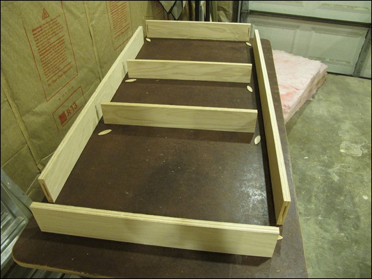
This article describes how I constructed these modules. They were built to match the current S-Mod standards, which matches what our club uses. The frame work was made out of 3/4"-thick Birch plywood. I cut the outer boards to 4 inches wide, and the two inner boards to 3-1/2" wide. Biscuit slots were cut next. After dry-fitting the assembly, this is what I had.
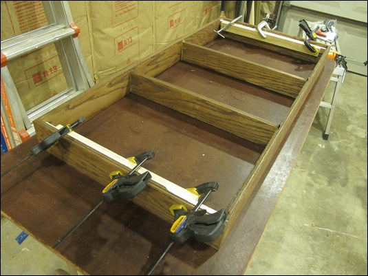
After the glue dried, I stained the frame. After three coats of lacquer, it was time to work on installing the top board. We decided to use 1/2" insulation foam as the top for some of our recently-built modules to hopefully cut down on the weight. The insulation board was to rest on the two inner board, which is why they were cut to a 3-1/2" width. My plan was to route a groove on the inner edge of the outer boards using a rabbeting bit. However, it turned out that it just doesn't work on plywood. If I had made the frame out of solid wood, this would have worked (however, solid wood makes a module much heavier, as well as more sensitive to temperature and humidity changes). Instead, I decided to glue in some strips against the inside end boards to provide the support needed for the top board. This is what I was doing in the next photo.
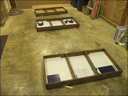
I then cut and installed the insulation boards into the framework. I also added some additional support boards underneath to provide maximum support for the foam boards (which turned out to be a blessing later on). The next photo shows the three modules' glue drying. I used "Foam Board" glue for all insulation board installations.
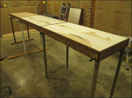
I cut some legs following our club's standard, and temporarily clamped them to the modules. Some of the foam had a thin metallic coating, which turned out to be fairly easily removable, and provides a better gluing surface (i.e. directly to the foam).
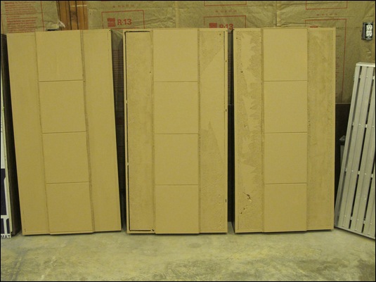
For the sub-roadbed, one can use Homasote insulation material, but that is rather difficult to find in the Houston, Texas area, and it is also somewhat expensive. For my home layout I used ceiling tile, which worked well and easy to find in the local hardware store. I decided to use ceiling tile for the club's modules as well, sticking to the philosophy of making the modules as light as possible. The plain, flat ceiling tiles are best for this. They do leave a joint gap, but that is easily hidden later on under ballast. After the glue set, I cut the sub-roadbed profile and painted the surface of the modules to provide a basic "ground" color and to protect the ceiling tile from moisture.
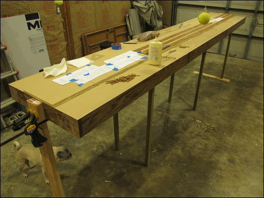
Together with a print-out of the track plan (shown above) and multiple copies of Fast Track's #6 S-scale turnout templates, I marked off where the track was to be positioned. Note that the two center tracks need to match up with the S-Mod standard so that we can potentially use these modules elsewhere in the club layout. The next photo shows a good number of ties down already. Our club has all hand-laid code 100 track, so these modules will be hand-laid as well (note our Pug investigating what I was doing in the garage).
With all the ties down, it was now time to stain them. I typically use a Minwax stain; something close to the color ties have with creosote applied to them. Much like in the real world, the stain protects the wooden ties.
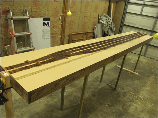
I had trimmed the sub-roadbed to match where the outside tracks' ties were to be placed, but I had not trimmed the front end where all the turnouts are, so that was done next. I then wanted to have some coal-like ballast base, so I glued that in place (it wound up not really being visible in the end).
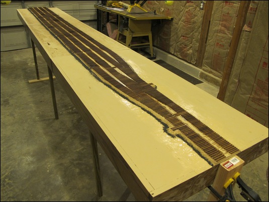
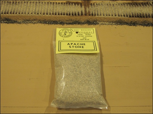
We strive for a smooth, cohesive look to our club modules, but it seems that over the decades the color of ballast has been somewhat "flexible". I decided on using Arizona Rock & Mineral's "Apache Stone" for the ballast. It was the closest match I could find to one of the club's original modules. It is somewhat bigger than the company's HO-scale "mainline ballast", so it is a better match for S-scale, I think. I prefer ballasting before laying rail, so the modules were ballasted and allowed to dry overnight.
For the actual laying of track, I moved the operation indoors because it was still quite warm in the garage in Houston in October. I started with the center module, which is the easiest, i.e. no turnouts. I left 2 inches of ties without track because of the bridge rails that get installed during a show.
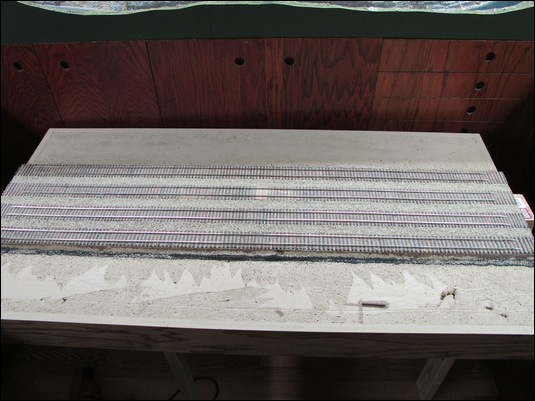
With the center module done, and using another club module I had available, it was easy to mark off exactly where the rails needed to be to get them to fit. I marked both of the other modules that way. I spiked some short section of rail temporarily where the bridge rails would go, and then used them as a guide as I laid the modules' rail indoors.
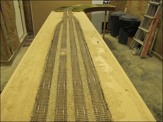
The end module (the one with the two turnouts) took me two days (full time) to complete. The first module, shown below, took me three days (10+ hour days) to lay the track.
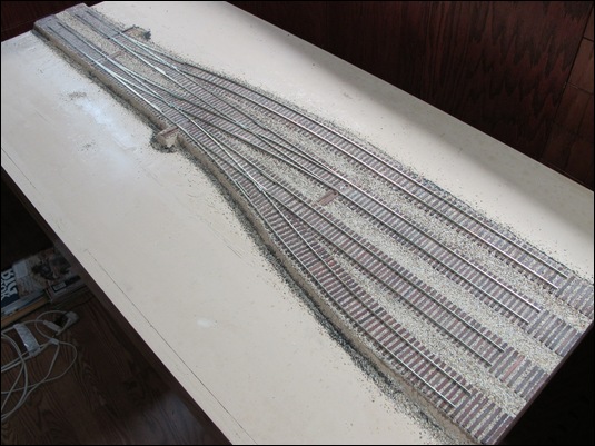
The day before the show set-up, this is where things stood. I had brought the three wye modules to the house from storage. I set them up in the garage (it all barely fit; I'm standing in the door way to be able to take this photo). The overall size of this set-up is 8 feet wide by 17 feet long. At this point I had completed the legs based on our club's standard, but neither the track wiring nor the scenery were done. The pressure was on. I had soldered feeder wires to each individual piece of rail as I laid the rail, but I still needed to install the bus wiring. Before I did the set-up shown in the photo below, I had completed the installation of the Fast Tracks' Bullfrog manual turnout controls (a full day project in and of itself). You can see the handles for the turnouts in the holes on the side of the modules.
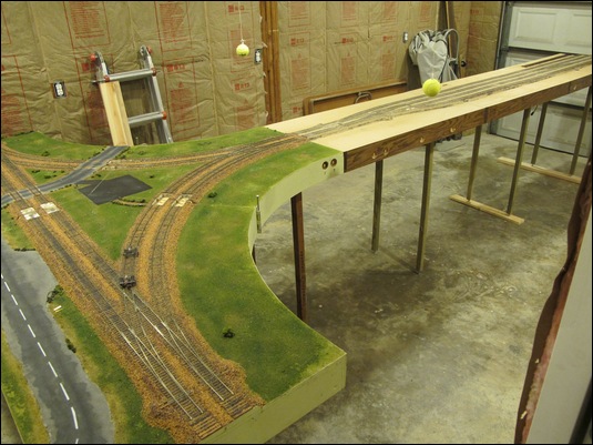
I installed wheelstops at the ends of each rail. I have used these for years on my own layouts, but some members expressed concerns about their durability both during module transportation and while attempting to stop a train at speed. We'll have to see how well they'll last.
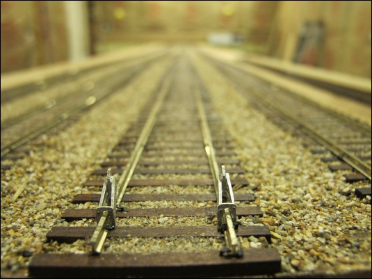
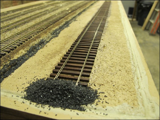
Some of our club's members have some engines that do not have a DCC decoder installed yet. It is possible to run one engine in analog (i.e. DC) mode, but only one. What I found was that usually when a member has completed a run using such an engine, he puts the engine on the scenery to remove it from the track. I decided to add a 3-foot section of unpowered track to the last module. I ran out of code 100 rail (used a little over 100 real feet of rail on these three modules!), so I used code 83 rail. This close-up photo shows one end of the dummy track with a pile of coal glued in place. The other end has a tie placed over the rail.
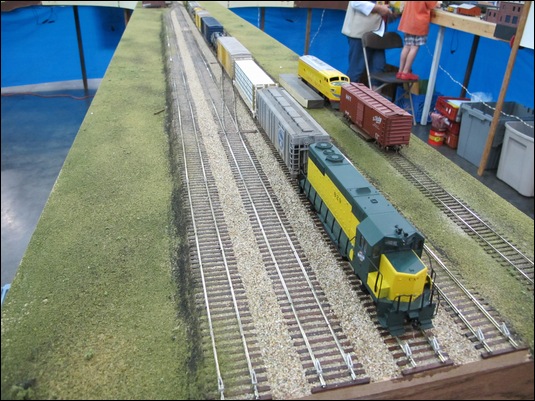
I finished debugging the modules late the night before the show set-up day. Even though this page may make it look easy, I spent a solid three weeks working on these modules, usually 6 days a week, full-time, to get them finished in time for the show. The photos below are of the wye and the "third leg" modules on October 8, 2011 at the "Big Texas Train Show". As you can see, the staging tracks are being used, as well as the dummy track. I installed a Digitrax UP5 panel in the first module to make it easy to plug in a throttle and to select an engine while you are near the staging tracks. I just put a basic layer of ground foam on the modules, so that will need to be enhanced in the future. I also didn't have time to paint the sides of the rail. Some of the turnouts need a little tweaking here and there, so that will all be done before the next show. By the way, the modules, as finished in these photos, weigh 18 lbs each. They functioned perfectly throughout the two-day show.
